Creating in 3D is about more than just geometry. Cameras, lights, and materials are important parts of creating a visually interesting 3D scene. p5.js has a number of tools that make it possible to transform the appearance of our geometry.
Camera and view
The camera is an essential piece of a 3D scene. It gives us a sense of space and dimension and helps us frame our content. WebGL mode provides a perspective camera by default, but we can change this using the perspective() or ortho() functions.
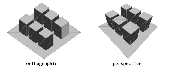
An illustration showing the difference between perspective and orthographic camera types. In the orthographic view, lines move parallel to each other, where in the perspective view, lines converge.
A perspective camera skews objects so that they appear smaller as they get further away, vanishing at a single point in the distance. This is in contrast to an orthographic camera, where the geometry stays the same size as it gets further away and has no vanishing point. You can play around with both options in the example below.
Field-of-view, or FOV, is the term used to describe how much our camera can see, measured in angle. In simple examples, it might appear to have a zoom-like effect, but larger FOV angles cause shapes to have more perspective distortion. Sometimes, this effect is used for artistic purposes.
Another important term to understand when working with cameras in 3D is the camera frustum. The frustum of the camera is the shape of the camera’s view. It is a pyramid-like shape within which geometry will be displayed. The frustum includes two components, a near plane and a far plane. The near plane defines the minimum distance that geometry must be from the camera to be rendered. The far plane defines the maximum distance that the geometry can be from the camera and still be seen. Each of these can be changed to affect how close and how far the camera can see. This process of selectively including geometry is sometimes referred to as “clipping.” You can set these using perspective() like so:
    perspective(
  fieldOfViewY, // Angle, in radians
  aspectRatio, // width / height
  nearPlaneDistance, // Minimum distance from camera
  farPlaneDistance // Maximum distance from camera
);
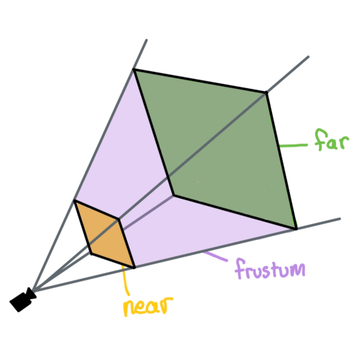
An illustration showing the camera frustum in purple, the near plane represented by a yellow rectangle near the camera, and the far plane as a green rectangle on the opposite end of the frustum volume.
You can move cameras by passing arguments to camera(), but constantly moving and adjusting the camera in code can be tedious. orbitControl() can be used to zoom, pan, and position the camera using the mouse. You can use it by calling it at the beginning your draw() function, outside of any push() and pop() calls:
Try building a sculpture out of cubes that looks like one thing from one side, but something else when you orbit to a different side.
Lighting
Light is another essential part of a 3D scene, helping convey shape and depth. p5.js has a few different types of light that can be used in a sketch:
ambientLight(): Ambient light makes everything display a little brighter, with no consideration for light position or direction.directionalLight(): A directional light is a light without a position that shines from a single angle, which can be especially useful for communicating depth in a scene, or when a scene needs a ‘sun’ light. This function accepts color and direction arguments.pointLight(): A point light emits light from a single point in all directions, similar to a lightbulb. This function accepts color and position arguments.spotLight(): A spot light emits light from a single point in a single direction. This light is cast in a conical shape and its radius and concentration can be adjusted.imageLight(): Using an image as a light source is like placing your scene inside a huge sphere textured with that image, sending light into the scene.noLights(): Makes it so that all subsequently drawn geometry is rendered without any lighting. This can be useful when you want flat, unshaded geometry.
These lights should be used within draw(). One image light and up to 5 lights of each other kind can be used simultaneously per shape drawn, allowing you to compose a scene with varied and complex lighting sources. You can also contain light functions within push() and pop() to contain lights to just one section of code, allowing you to use a different set of lights for another shape. Since lighting is done per shape, each object in a scene will not cast shadows on other objects.
Try checking and unchecking the boxes in the following interactive example to see how lighting can be blended together. For each active light source there are visual indicators of their position or direction, just know that these are here for illustrative purposes!
Comment and uncomment each light and experiment with their parameters.
Materials and textures
Objects can appear different based on their material properties. Materials dictate how light interacts with the geometry and how color (or texture) applies to the object. Materials can be varied, making objects shiny, rough, or textured with images.
There are five material properties in p5.js that combine to control the look of an object:
fill(): This is the color used when there are no lights in the scene. When lights are added, this color mixes with the diffuse component of the light: the bright and dark areas of the surface due to light being directly cast on it.ambientMaterial(): This is a color that mixes with theambientLight()set in the scene. If it is not set, this will be the same as the fill color.specularMaterial(): This is a color that mixes with the specular component of the light: the reflected highlights on the surface of the shape. If this is not set, there will be no highlights on the shape.shininess(): This number represents how sharp the specular highlights are. A value of 1 gives spread-out, blurry highlights. The higher the shininess, the sharper and smaller the highlights get. This only makes a difference if a specular material has been set.emissiveMaterial(): This is a color that gets added to the shape. It represents the light that the shape produces on its own, so it does not vary based on the other lights in the scene.
To determine the color of each pixel, each material component interacts with the scene’s lights before being added together.
There is one other material setting called normalMaterial(). If this is set, all other material settings are ignored, and the color of the shape is based on the angle of its surface. If the surface is angled horizontally, it will appear more red. If it is angled vertically, it will appear more green. If it is angled towards the camera, it will appear more blue. This is often helpful for debugging shapes.
In the interactive example below, try selecting each of the different materials to see how they affect the appearance of the geometry.
Comment and uncomment the different lights in this example to see how they interact with the materials:
In WebGL mode, you don’t need to have a single fill() value for the whole shape: you can apply a different fill color to each vertex. If the vertices of a triangle have different fill colors, the triangle will smoothly blend between the colors on the corners. This is a useful way to create smooth gradients across shapes, like in the example below. Try clicking and holding on the canvas to see the edges of the shape to get a sense of where WebGL is filling in the in-between sections for us.
More custom materials can be achieved by using the texture() function. This allows you to map an image to the surface of a geometry. These textures can be imported from an image and even generated within code using shaders. To map a texture to your geometry, use loadImage() within preload(), then call texture() before drawing your shape.
When you create custom geometry you can specify a texture coordinate for each vertex after each 3D position. By default, these coordinates are in pixels relative to the texture you have applied, but you can set textureMode(NORMAL) to use a 0-1 range, representing a fraction of the image’s dimensions, which is helpful in making models that work for any image.
The texture coordinates of a vertex can stay the same while its 3D position changes. You can use this to distort and animate images. In the example below, changing vertex positions while keeping texture coordinates the same is used to wiggle a drawing. Click and hold on the canvas to see the edges of the grid of vertices being drawn.
By distorting vertex positions, can you make an image of a character look like it’s jumping? Waving? Walking?
Conclusion
Having control over the camera, lighting, and materials will give you more flexibility to change the look of your sketch and open up the possibility for you to introduce your own style to your 3D sketches.
To make even more advanced materials for your shapes, artists often write shaders. Check out the Introduction to Shaders tutorial when you’re ready to explore even more possibilities!
Glossary
Camera
The viewpoint of a 3D scene
Perspective
A camera projection that gives the appearance of depth, achieved by making objects in the distance appear smaller.
Orthographic
A camera projection that is orthogonal and unaffected by depth. It gives the appearance of being two-dimensional.
Field-of-View
The angle representing how much can be seen by the camera.
Frustum
The geometric shape representing the full area that can be viewed by the camera.
Near and Far Plane
The near plane represents the minimum distance a geometry must be from the camera to be displayed, while the far plane represents the maximum distance.
Clipping
Selectively showing some geometry and not others, such as when geometry falls outside of the camera frustum.
Diffuse Light
The effect of light on a matte material. Since matte materials bounce light equally in all directions, the color you see will look the same regardless of your vantage point.
Specular Light
The effect of light on a shiny or glossy material, visible as reflected highlights. The positions of the highlights will change as you move around an object as the reflection angles change.
Shininess
How sharp the specular reflections on an object are. This property comes from how much reflected light spreads out after bouncing off of the surface of an object: the less it spreads out, the sharper the reflections and the shinier the object appears; the more it spreads out, the blurrier the reflections are and the less shiny the object appears.
Emissive Light
Light emitted from the surface of an object, which gets added to the light that comes from external light sources.
Ambient Light
A uniform amount of light coming from all directions, as if the scene were inside a big sphere emitting light.